samedi 6 avril 2013

Discovering the Raspberry Pi / Gertboard - Part B

Décembre 2018: Mes articles sur ce site date de 2013!
Je les ai tout de même laissés, ils ont peut-être encore une utilité.

Il vaut mieux consulter ce site: http://Mon livre sur Java, Python et le Raspberry Pi 3

A first example with the Gertboard

>>>>>>>  D'autres articles disponibles sur http://www.boichat.ch

The Gertboard revision I have used is marked 21 Oct 2012.

The related Gertboard User Manual document version 2.0 (Gertboard_UM_with_python.pdf) describing the hardware can be found in
http://raspi.tv/downloads

Playing with the Gertboard leds


The Gertboard fits directly onto the GPIO pins of the Raspberry Pi via a double row of pins socket on the back of the Gertboard.


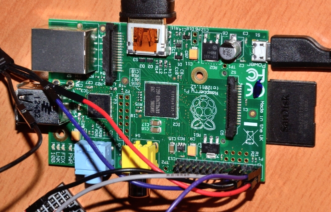
We can see some leds active on the top.
The straps (the coloured wires) and jumpers as explained in this nice tutorial here:

http://www.tech-fruits.com/all-tutorials/the-gertboard-lesson-2-testing-the-buffered-io-section/

where we can find everything about the hardware and the software. This is not my intention to repeat here this information.

The wiring diagram for the LED test program is also described in the Gertboard User Manual at page 21.


To download the Gertboard C software, we can go for instance to the Web site http://www.element14.com.

I have downloaded the file gertboard_sw.zip into my Raspberry working directory and to install and compile the software:

unzip gertboard_sw_20120725.zip
cd gertboard_sw
make all

and to execute the program:

sudo ./leds


We could have a look at the leds.c source code to see how patterns are used for the leds and maybe understand what happens if we do not have enough wiring cables between the "GP" and "B" pins.


vendredi 5 avril 2013

WiringPi for the Raspberry Pi

Décembre 2018: Mes articles sur ce site date de 2013!
Je les ai tout de même laissés, ils ont peut-être encore une utilité.

Il vaut mieux consulter ce site: http://Mon livre sur Java, Python et le Raspberry Pi 3


Using WiringPi for verifying our relay

The small complete project described in

A STARTING POINT WITH RASPBERRY PI

could use the WiringPi package for testing the relay.

The WiringPi is a library part of the Gordons projects described in https://projects.drogon.net/raspberry-pi/wiringpi/

The installation

In case our Raspberry Pi software is not up-to-date, it's better to do:

sudo apt-get update
sudo apt-get upgrade

The git sotfware is a revision control and source code management which may need tp be installed on the Raspberry: 

sudo apt-get install git-core

The Drogon projects has a repository for WiringPi which can be downloaded and installed:

git clone git://git.drogon.net/wiringPi

Then, when done, we can see that the directory /home/pi/wiringPi has been created
and we should built it:

cd wiringPi
./build

The WiringPi is coming with a C/C++ library and some examples. The gpio utility is also provided in order to run GPIO command directly from a terminal.

Testing our relay

As explained in http://jbbraspberrypi.blogspot.ch/2013/03/discovering-raspberry-pi.html the relay is connected on the GPIO 14 and the gpio following command can be used to deactivate or activate the relay:


gpio -g mode 14 out
gpio -g write 14 0
gpio -g write 14 1

The parameter -g indicates that the pin numbers are interpreted as BCM_GPIO pin numbers rather than standard pin numbers.

samedi 30 mars 2013

A first software installation on the Rasperry Pi

Décembre 2018: Mes articles sur ce site date de 2013!
Je les ai tout de même laissés, ils ont peut-être encore une utilité.

Il vaut mieux consulter ce site: http://Mon livre sur Java, Python et le Raspberry Pi 3

Screenshots on Raspeberry Pi

>>>>>>>  D'autres articles disponibles sur http://www.boichat.ch

After we have created our first SD card, booted it and run the setup procudure, we had the need to install the necessary software to make screenshots on the Raspberry Pi itself and to transfer them on a PC for documenting correctly our blog articles here!

The requirement

A Linux tool on our LXDE desktop environment to make screenshots and why not scrot!


Installing scrot

We can use either the terminal console on the Raspberry Pi or the Windows putty.

We should first run an update on our Raspberry Pi:

sudo apt-get update


The scrot application can be installed with:

sudo apt-get install scrot

and we should answer Y for yes to:

Do you want to continue [Y/n]? Y


The program scrot is now install, and we can execute it from putty or from an LXTerminal on the Raspberry Pi:

scrot for immediate snapshot or with scrot -d 5 for instance after a 5 seconds delay usefull for rearranging or closing some wimdows.

The png file is available in the form 2013-...._1360x768_scrot.png which could be transfered to a Windows PC with WinScp.

ssh and scp on the Raspberry Pi from Windows

Décembre 2018: Mes articles sur ce site date de 2013!
Je les ai tout de même laissés, ils ont peut-être encore une utilité.

Il vaut mieux consulter ce site: http://Mon livre sur Java, Python et le Raspberry Pi 3


ssh and scp on Windows for Rasperry Pi 

>>>>>>>  D'autres articles disponibles sur http://www.boichat.ch

  • ssh allows to access the Raspberry Pi from ouside in console mode

  • scp allows to transfer files between the RaspBerry Pi and an external computer


References for installation:

We can select an installer or copy the software directly into a directory we should remember for later execution!

The IP address of the Raspberry PI 


Before using ssh or scp, we need to find out the IP adress using sudo ifconfig:


The IP address is here 192.168.1.40


ssh (secure shell) with putty

We can start the putty.exe application for instance from the Windows command start:


Here we have already defined a saved session: no need to retype the IP address.

We can now enter the user pi and the password raspberry if we didn't change it in the first setup:


The session is now active and we can now work in the same way as in a terminal session directly on the Raspberry Pi:


Useful commands and configuration:
  • Ctrl-L to clear the content of the window
  • Click on the tittle bar with the right mouse button, change settings..., Window appearance, Font, and for instance Courier 12 points


scp (secure copy) with winscp

We can start the WinSCP.exe application for instance from the Windows command start:


This is the same as for ssh, with the ip address, the iser and the password, and we can save our configuration fpr later use:


When connected we will see the two parts where we can transfer files in one or another direction:


There are many sites on Internet where we can find a number of good descriptions.
This one is particular impressive: http://winscp.net/eng/docs/start


vendredi 29 mars 2013

A first boot on the Raspberry Pi

Décembre 2018: Mes articles sur ce site date de 2013!
Je les ai tout de même laissés, ils ont peut-être encore une utilité.

Booting our SD card on the Raspberry Pi

>>>>>>>  D'autres articles disponibles sur http://www.boichat.ch

After we have created our first SD card, we can now boot our system on the Raspberry Pi.

The material


On the left side, we need to connect an USB mouse and an USB keyboard. The Ethernet cable for accessing the local network and the Web will be required to add more software from the Internet.

On the top we see the HDMI cable connected to a display with HDMI capabilities.

Finally on the left the micro USB cable to get the power for our device and our SD card coming from Preparing the SD card. We decided to use a 4 Gbytes SD card which is about twice the size of the original size, allowing us to have sufficient space for more applications and data.

The first boot

As soon as we boot the system, we should see the display active showing a huge number of progress messages indicating that the Kernel is booting.

At the end this ncurses based raspi-config tool should appear in order to setup the system:


With ncurses, we cannot use the mouse but the cursor keys like up and down on the keyboard, as well as the return key. The left and right cursor keys allow to select the final <Ok> or <Cancel>.

A number of things are absolutaly required at this point:
  • expand_rootfs to extend the system to fill the SD card.
    The extension will be done on the next reboot.
  • configure_keyboard to set the keyboard. If we don't do it, we could have then surprises with characters like y, z, -, _, and other characters, if we don't have an Englisch keyboard.
    A number of varietes of keyboards, like the Generic 105-key and languages will be presented.
    For swiss French keyboard, we need to select first the German (Switzerkand).
    For the AltGr we can keep the default. No compose key too.
    We will allow tu use the Control+Alt+Backspace to stop the X server.
  • change_pass can be done to change the installed user und password which are pi and raspberry.
  • change_timezone is recommended to be on the right place on the planet earth!
  • ssh is a must to be able to access the board later from the PC. We should se the message: SSH server enabled.
  • boot_behavior allows to start the desktop environment and not in console mode.
    We should set it to Yes.   
We can stop the Raspi-config with the <Finish> selection and the return key. A "Would you like to reboot now?" ist presented and we should select agaib <Yes>.

A a later stage, wenn the system has been already partialy setup, we could run again this configuration with sudo raspi-config.


When everything is ready, we can reboot the system to get the Raspian LXDE desktop environment:


mercredi 27 mars 2013

Starting with the Raspberry Pi - SD card

Décembre 2018: Mes articles sur ce site date de 2013!
Je les ai tout de même laissés, ils ont peut-être encore une utilité.

Preparing the SD card

The first thing to do is to get the Linux software and to write it on an SD card.
We can do it actually before getting the Rasperry Pi board and material, and the day we receive it by post, the system could be running after 5 or 10 minutes of impatience!

We will describe here how to do it on Windows and with a 4 Gbytes SD card which is about twice the size of the original distribution, allowing us to have sufficient space for more future applications and data.

Getting the software


The Linux image file can be downloaded from http://www.raspberrypi.org/downloads and the Raspbian “wheezy” can be selected, for instance 2013-02-09-wheezy-raspbian.zip and then downloaded.
The Zip file contains the image 2013-02-09-wheezy-raspbian.img. This is can be extracted and written on the SD card. We will describe here how to do it on Windows.

Getting the win32diskimager-binary software


This Windows application can be found in http://sourceforge.net/projects/win32diskimager/. This is not a traditional Windows installer and needs to be unziped into a subdirectory where we have our Rasperry Pi Windows PC working environment (here for instance D:\Raspberry\win32diskimager-binary\),

When executing Win32DiskImager.exe we get this:


We see now that we need to specify the image file and the drive where a 2 Gbytes SD card has been inserted. Myself I use a cheap USB 3.0 multi card which is faster and particular interesting when transfering picture files from a camera.


When everything is ready we get this:


Using the Windows explorer, we can then decide to rename the CD card for instance to WHEEZYFEB13, to remember later what is on the card, und even to check the content to find out a number of files with the 09.02.2013 date, the creation date of this Raspian Linux.

As usual, we should eject the SD card with the Windows gadget!

More articles:

dimanche 24 mars 2013

Discovering the Raspberry Pi - Part A

Décembre 2018: Mes articles sur ce site date de 2013!
Je les ai tout de même laissés, ils ont peut-être encore une utilité.

Il vaut mieux consulter ce site: http://Mon livre sur Java, Python et le Raspberry Pi 3

A starting point with Raspberry Pi

>>>>>>>  D'autres articles disponibles sur http://www.boichat.ch


After I got this nice project running successfuly, I decided to write in a blog sufficient information to help beginners with Raspeberry Pi to become familiar with its hardware and software. There are already so many articles on the Web doing more or less the same thing .... but why not again and probably differently!

Being able to switch on or off a 220 Volt home appliance using the light level in the room


So many things have been done before reaching this first running project including:
  • Getting the hardware
  • Installing the software
  • Describing all sort of difficulties before getting my bedside lamp reacting on light level changes in the room
  • Adding features inside and outside to extend this project
The idea is also for the author to collect all possible information in order to be able for him, or other interested "players of this Rasperry Pi game", to find out the essential!

The different parts

This is the sensor part to get the light level:

Photo-resistance circuit

This is the relay to switch on a 220V light or anything else connected for instance to a light bulb cable:

220 Volt Relay

And both connected to the Raspberry Pi board:


The code

The following Python code to deal with this project is more or less some copy/paste from different projects, in particular from:
http://www.raspberrypi-spy.co.uk/2012/08/reading-analogue-sensors-with-one-gpio-pin/


#!/usr/bin/python
# Reading an analogue sensor with a single GPIO pin
# Set the relay on off according to the light level

import RPi.GPIO as GPIO, time

# GPIO library to use Broadcom mode
GPIO.setmode(GPIO.BCM)

# Charge time measument
def RCtime (PiPin):
  value= 0
  # Discharge capacitor
  GPIO.setup(PiPin, GPIO.OUT)
  GPIO.output(PiPin, GPIO.LOW)
  time.sleep(0.5)

  GPIO.setup(PiPin, GPIO.IN)
  # Count loops until voltage across
  # capacitor reads high on GPIO
  while (GPIO.input(PiPin) == GPIO.LOW):
    value+= 1

  return value

GPIO.setup(14, GPIO.OUT)

# Main program loop
while True:
  lum = RCtime(4)
  print lum # Measure level using GPIO4
  if lum < 360:
     print 'High light'
     GPIO.output(14, False)
  else:
     print 'Low light'
     GPIO.output(14, True)


The relay

This is the part dealing with the 220V relay. On the picture, we see that 3 cables are connected (one of the 4 is not required):

·        Yellow - the GPIO pin
·        Red - the 5 Volt power
·        Black - the ground

The wire for the 220 Volt goes to the green connector. A 220V extension cord with 2 o 3 (with ground) wires can be prepared like this:


There is a very nice description of the pins in this Web site:


The pin 8, the fourth from the right on the external side:


correspond to the BCM GPIO pin 14 (see the Python code). The pin 2 is the 5 Volt required for the relay.


Testing the relay

This is actually recommended when building a project with different parts.
Here a small program for verifying our relay:


#!/usr/bin/python
import RPi.GPIO as GPIO, time

print "Start"

GPIO.setwarnings(False)
GPIO.setmode(GPIO.BCM)

PiPin = 14
GPIO.setup(PiPin, GPIO.OUT)

GPIO.output(PiPin, True)

time.sleep(2.0)

GPIO.output(PiPin, False)

print "End"


There are many different ways to test this relay.
This could be done using C++ or directly accessing the GPIO from a Terminal session.

There is an interesting article with nice pictures here:
http://hertaville.com/2012/11/18/introduction-to-accessing-the-raspberry-pis-gpio-in-c/

The sensor part

The cables required are:
·        Purple - the 3.3 Volt for the power
·        Black - the ground
·        Grey - the GPIO pin to measure the lightsensor

A complete and nice description here:


There is no need to copy/paste it here! 


A view from inside of the pins may help too:


The first pin is the 3.3 Volt and the fourth the GPIO4.


More articles:


And with the Gertboard: